LowTek Arduino CAN-Bus
I finally found a nice project that would give all my playing around with Arduino some focus. I've moved from standard boards to breadboard a while ago and I have a whole bunch of 'em, but didn't really know what to do with them. First and foremost, I didn't have an easy way to build a network of Arduinos -- and there's only so much to be done with a single one that can't really communicate to the outside world.
Fortunately, my employer is a company that builds embedded devices connected to a CAN Bus, and I decided to try and build one for myself. Such a network would then allow for a much wider range of interesting things to do. For starters, I'm going to control a Lego train — and I can even use my power supply for that!
So that's the idea. However, the "real" CAN bus seems to require a more complex hardware setup than seemed practical for reproducing across a set of breadboards, so I tried to find a way around that. The result: The Poor Man's CAN bus!
CAN primer
First of all, here's the gist of how CAN works. CAN is a near-realtime, multi-master bus that handles collisions in a way that more important messages survive the collision. Messages consist of an 11-bit ID and an 8-byte payload.
Near-Realtime means that each transmitted message is short in nature, so that transmitting it doesn't take long and the bus is usually not busy. The result is that there's usually not much waiting involved.
Multi-Master means that there is no designated master that controls the flow of communication.
-
Collision handling is based on message IDs. The message ID also denotes the importance of each message, and message IDs must be unique across the bus so that in no case, two devices try sending messages with the same ID.
Each bit is held long enough on the bus so that all controllers on the bus have had a chance to receive it. That means that bus length is directly limited by the bit rate: The current bit must have reached all controllers before the next bit time slot.
This allows for bits to be killed: If one controller writes 1 and another one writes 0, the bus's value is 0. Now say two controllers want to send a message at the same time, one with the ID 23 and one with 42. These are the bits that they're going to transmit:
Alice: 23 = 00000010111
Bob:   42 = 00000101010
Now, the ID phase works pretty much like poker: Everyone around the table is going to fold at some point and the last one left wins. So when Bob sending the 42 tries to send his 1 value and Alice kills that bit by sending a 0 at the same time, Bob knows that someone else has a more important message to send. Bob will then refrain from sending his message, wait for the next frame and try again.
The Hardware
Building a piece of hardware that does this is actually pretty easy. You need two Arduino pins: One to send a value and another one to monitor the bus and see what the others are doing. The important part is that we need to make sure that when two controllers write different values, the zero always wins.
That's actually easily achieved using a pull-up resistor and a diode, like this:
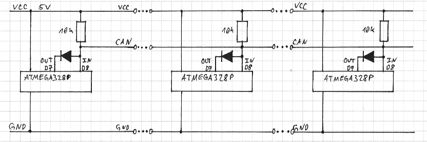
So when a device sets its output pin LOW, the whole bus is pulled down to LOW. The diodes prevent the bus from being shorted when other devices set their output HIGH at the same time. And with that, we can already implement the complete protocol!
The Software
I wrapped a state machine that handles the basic protocol in the CanDrive Arduino library that can then be used in other sketches. Here's the CAN bus part of my rail switch controller:
void loop(){
    uint16_t recv_id, recv_val;

    can.handle_message();

    if( can.recv(&recv_id, &recv_val) ){
        if( recv_id == 450 ){
            digitalWrite( (recv_val == 0 ? 13 : 12), HIGH);
            digitalWrite( (recv_val == 0 ? 12 : 13), LOW);
        }
    }
}
So when the CAN bus receives a message with ID 450, it configures the GPIOs to switch the rails in the direction indicated by the message value. Sending such a message then boils down to:
void loop(){
    if( have_something_to_say ){
        can.send(450, 1);
    }

    can.handle_message();
}
That's it.
Real-life application
I prototyped the whole thing on a breadboard with a CAN bus of about 5 cm in length, and I was not at all sure how the thing would behave once I deployed it in my application, a Lego train. It would need to cross underneath the tracks, it would have to connect three or four breadboards, one of which holding the power supply — so there are lots of potential sources for interference that could corrupt the messages. Hence, my expectations weren't really all that high when I first put the whole stuff together.
I'm glad to say that it just works. The power supply sometimes complains about CRC errors, but since I send the power levels two times per second anyway, I don't really notice losing a message there. All the other components will have to acknowledge commands, so I guess losing the occasional message won't be that much of a problem.
Currently, I'm trying to connect the whole thing to a Raspi so I can implement a more intelligent controller and connect the whole thing to a network. Unfortunately I couldn't get either SPI or Serial to work correctly and I haven't managed to find out why so far. This sucks, but I won't give up now :) I'm determined to get this stuff running.
Update: The next morning it occurred to me that in order to use the Raspberry's Serial pins, maybe I should first disable its serial console that is by default bound to exactly those pins -- and immediately, all the randomness vanished that had bothered me before. Duh.