Revisiting the Arduino power supply
I finally got around to completing my power supply.
I had worked on building a bench power supply powered by Arduino a while ago. I used a DAC to feed a 741 OpAmp, which in turn regulated the output via a power transistor. That worked okay, but I had a couple of issues getting the correct output voltage and the power supply couldn't go below 3V or something, due to the fact that the 741 isn't rail-to-rail. Also, I wanted to have more than one output channel which would have meant adding more DACs, because mine only has a single output. (And I wanted to try out an RC circuit, after I had read that this should do the job.) I had also found a different OpAmp that would allow me to cover the complete range from 0V to VCC without having to use extra trickery.
So, I chose to start again from scratch on an empty breadboard. I wired everything up as shown here, and it worked pretty much immediately:
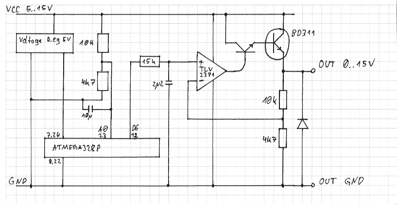
Port D6 outputs a PWM signal. The RC Circuit attached to it converts that to a voltage ranging from 0 to 5 volts, and the OpAmp and transistors amplify that up to the target voltage of 0 to 15 volts. (Target voltage is limited by the 10k and 4.7k resistors I use to measure the output voltage: Those need to be sized in a way that their output voltage is between 0 and 5 Volts to match the Arduino's range.)
So far, so good: I could produce an output voltage that would even be quite close to what I actually wanted. But I still had issues in getting that voltage to be correct. Under some circumstances, output voltage could differ by as much as 2 Volts from what I configured the Arduino to spit out. So let's take a look at the math again.
Finding VCC
First of all, I need to know the input voltage fed to the power supply. I'm using the internal vref, so the voltage seen by the ADC is:
That's the voltage spit out by the voltage divider, consisting of a 10k and a 4.7k resistor. So then VCC is:
Setting the Output
Initially, I figured that since that power supply circuit is essentially nothing but a big-ass intelligent resistor, it should suffice to set the PWM to the percentage of output voltage that I'd like to have. That kinda worked, but I always got that up-to-two-volts error, so that didn't work out. Instead, Wikipedia says an OpAmp amplifies the input voltage like this:
That explains why my stuff didn't work. So I need to use that formula to calculate the voltage I have to feed into the OpAmp. This voltage is in the range between 0 to 5V, controlled by the PWM:
And after I added those formulas to the sketch, I'm finally getting the correct results! :)